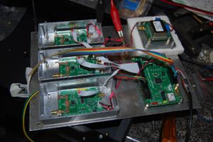
As the beacons in the Adelaide area for 23cm have not been replaced in the years after it had drifted way off frequency and then failed, it was floated that we in the Barossa area should create our own to fill the gap. I put up my hand for this and immediately looked to see what FM-828 based radios were around (had great success in earlier times with these). I bought crystals for what we thought the frequency would be ( 144.455, 432.455 ) and a plan was to use a transverter from 144 -> 1296 to get that band going.
Many thanks to Joe, VK7JG (now SK) for providing a Philips TX-810 chassis to be the base of the Mark I beacons
So the Mark-I beacon project kicked into gear, or should I say it stumbled from post to post as I lost my way with work commitments and other jobs around home.
A working 144 MHz prototype was put to air from my home but I had big problems with key clicks and wide band noise. Not some thing I wanted on my door step if I wanted to start working EME on 144 myself.
A transverter for 1296 was built and trialed but I had stability problems with the L.O for 23cm and had very chirpy keying and a bit of FM. More time lost in pondering what to do.
A new generation of PIC controlled signal generators started to emerge and some were being programmed as beacon exciters in and around 2013. The group down at Mt Gambier (VK5RSE) adopted these as a way to have frequency locked beacons (from a GPS standard). I shelved Mark 1 and rebuilt in the same chassis using these boards, one port had the 144.456 keyed carrier and the other the 1182 MHz L.O for the transverter, all locked back to a 10MHz OXCO, how could I go wrong?
Key clicks and more key clicks was my burden, along with some odd birdies from the synth, I made excuses at each club meeting but could not bring myself to put them on air at the clubs repeater site in this condition (my personal shame I guess) so close to my own home.
In mid 2016 a new style of beacon came to my attention, a cunning ham in New Zealand (ZL) had designed a programmable PLL board and a controller board that had an on board GPS to keep time LINK. This combination could create CW, JT65 and JT4 digital modes. After taking with the early adopters of these beacon board, I have shelved Mark II and we are on to Mark III now (December 2016)
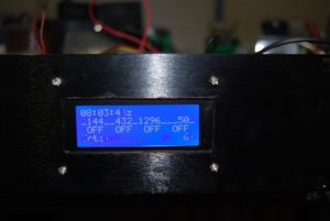
Mark III is being built into a 2RU rack cabinet, with the status digital display from the beacon controller showing up through the front panel. Power supply will be external and I hope to have 144, 432 & 1296 to air, at low power by the turn of the year. I have the 23cm P.A on hand just need to mount it and screw up a heatsink.
Hopefully Mark III will end my shame of having taken so long and provide a beacon that s quiet enough or me to keep being active on 144 & 432 MHz SSB.
Power Amps – have been built for 144,432 and 1296 with an extra P.A to come for a 50 Mhz beacon when we get approval to move from the original 50.315.
The 144 MHz beacon on 144.456 is operating live with about 15 W output into a single PAR omni Angle antenna
The 50 MHz beacon on 50.456 is operating live with about 15 W output to a HALO antenna.
the 23cm beacon needs an effective omni or semi omni with horizontal polarity, if you know of one please contact me on: vk8zlx at gmail dot com
Information about the original 50.315 MHz beacon can be found here: http://vk5brc.com.au/?page_id=2

